This is some ramble about how to get the most out of your oscilloscope without going too much into details. I will talk about analogue oscilloscopes mostly, as digital scopes are more straightforward but sometimes can be very problematic, just like driving an automatic car on icy road. I had a few of analogue oscilloscopes, like the OML-2M from the Soviet Union, and the RFT EO-213 from GDR, which I still have. Extremely reliable kits.
First of all, let’s be clear on what is an oscilloscope and what it does:
The oscilloscope (or just simply ‘scope) is a device that can show the voltage of an electrical signal/signals with respect to time. The scope has a cathode ray tube with a horizontal trace, which is called the timebase. The scanning speed of the trace is controlled by the ‘Time per division’ knob, which may be annotated as ‘ms/T’ or ‘Time/div’ or simply ‘Horizontal’. Voltage is measured by the vertical deflection with respect to the divisions of the screen. It is adjusted by the ‘V/T’ or ‘Volts/div’ or ‘Vertical’.
In order to make anything visible on the screen, the timing of the start of the timebase has to be perfectly aligned with the signal. This alignment is controlled via the triggering circuit: Yes, the timebase is started at each time how the ref pulls the trigger of a pistol on each start of a sprint race, hence the name.
How the triggering should be done? On old scopes, it can be done with either on rising or falling edge detection. There should be a switch for that. The exact voltage value where the triggering starts is set with the ‘Trigger’ knob. When the trigger level is outside the trace, the screen will run and not much is to be seen. Just adjust the trigger knob, and it should stabilise.
So, step-by-step:
Before connecting to the signal
-Adjust the ‘Time/div’ knob to the right value (say 1 kHz signal -> 0.5 ms/div)
-Adjust the ‘Volts/div’ knob to an approximate value (say 200 mV peak voltage -> 50 mV/div)
After connecting to the signal
-Set the ‘Trigger’ switch to rising edge
-Adjust the ‘Trigger’ knob until trace stabilises
Of course, on digital scopes you can just press ‘Auto Setup’ (or what I call the ‘Oh my god I am terribly lazy’) button, and the scope will adjust these things for you. Or not.
If it fails to set, setting it up boils down to the good old analogue method.
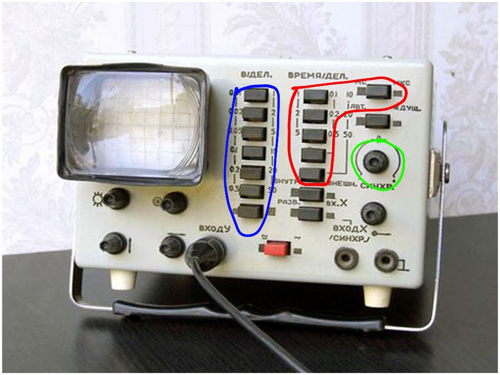
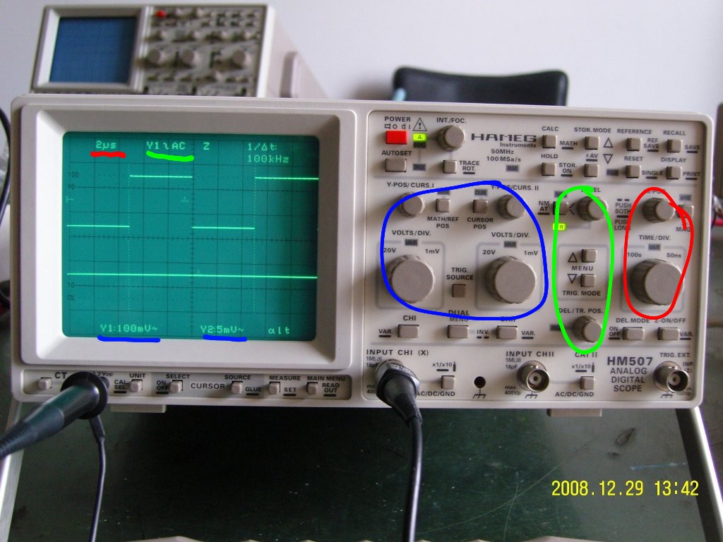
For the sake of simplicity, I have attached a few pictures where I annotated each sections with my graphics tablet. You can read the settings on the screen of a digital scope.
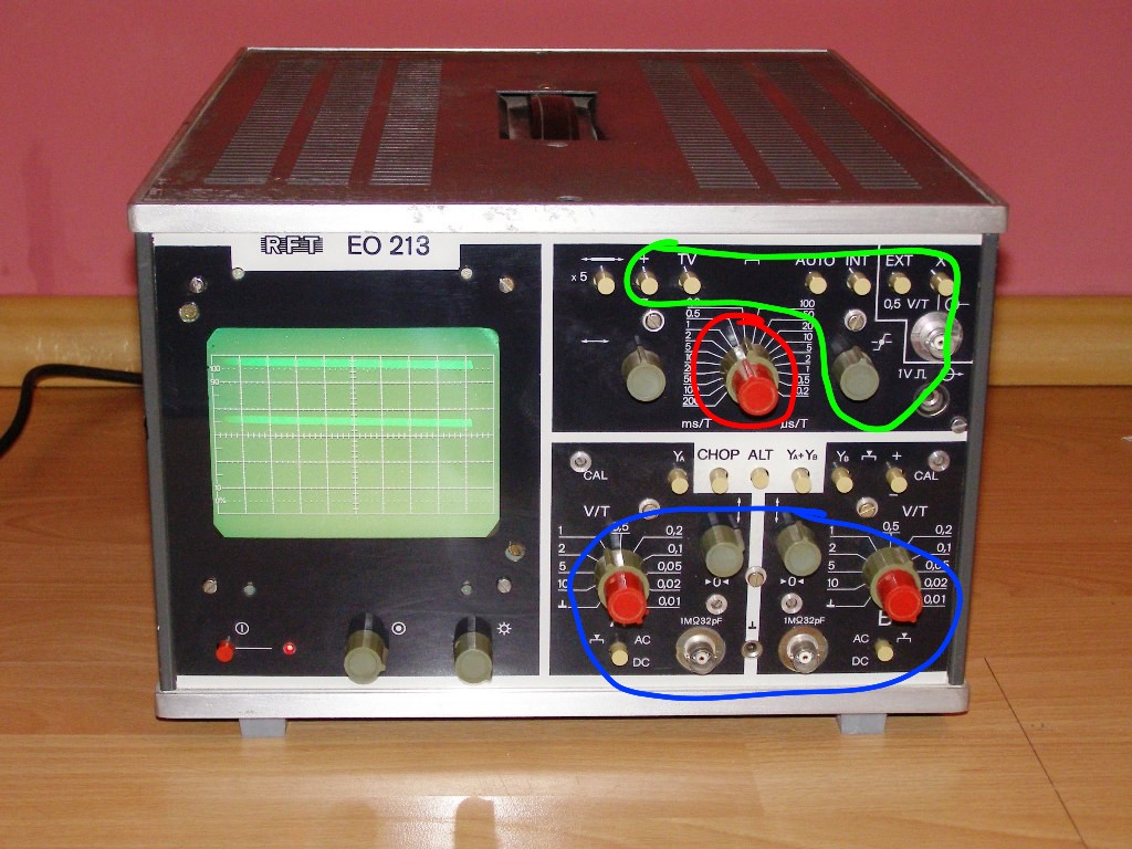
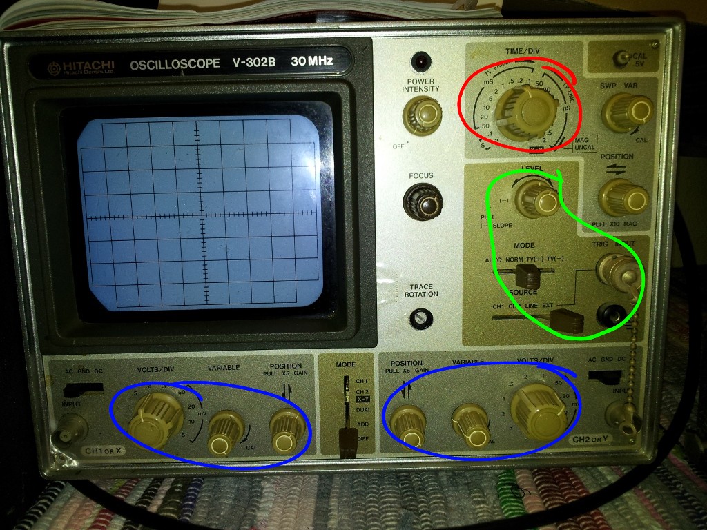
-Red: Time per division
-Blue: Volts per division
-Green: Trigger
The OML-2M was a low-end, single channel scope, with a modest amount of controls for triggering.
(Source)
The RFT EO 213 supports TV vertical sync pulse detection as well as analogue calculation of the two channels. Edge selection is done with the +/- button in the green area.
(Source)
Going West (well, East actually), the same category of analogue oscilloscope is not that different. A little bit more options, fancier design: you can select between TV lines, change the triggering source channel. You have to pull the trigger knob to change to falling edge. This Hitachi V-302B oscilloscope was donated to the ANARC radioclub:
(This is a picture I made, but you can use it freely…)
And when you are getting into up-to-date equipment, you will get into the wonderful world of digital scopes. The high-end ones run Windows, so triggering is just a problem of selecting from the menu. However, this HAMEG HM507 scope is interesting. It tries to merge the best of both worlds, allowing ‘analogue-like’ behaviour with the advantage of storing samples and time-related operations (such as averaging, persistence, etc.). Anyway, from this point the challenge moves from finding what knob is where on a current model to reading and understanding the contents of the screen. Which one is more difficult? Well, it depends 🙂
(Source)
If you’d like to have your scope added, let me know!







Fabulous Zoltan, thanks so much!