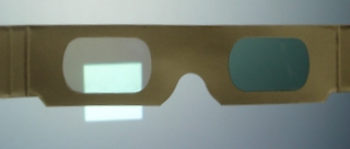
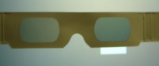
 The major drawback of a passive stereo display system like mine is the problem of “ghosting” or cross-talk between the displays. In theory, light from the left projector is completely blocked from reaching the right eye because it has the wrong polarisation. In practice, imperfections in the polarising filters, plus any depolarisation that occurs when the light passes through the rear-projection screen, will allow light to get through to the wrong eye. I did quite a lot of research before I bought my screen and polarisers from Screen Tech, precisely in order to minimise this problem. Once my system was up and running, I was keen to quantify the degree of the problem.
25th May 2006
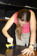
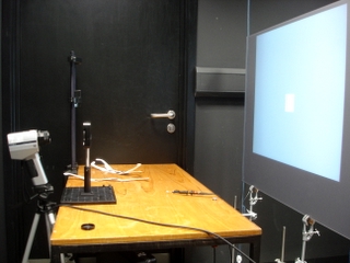
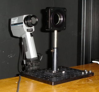
I arranged the photometer such that it viewed the screen through a polarising filter. I rotated the filter so that the light coming from the right eye’s projector was minimised. As detailed in the sections below, I then measured how much the light from the right eye’s projector continued to influence the photometer reading (obviously if there were no ghosting, it would not influence it at all). I read the photometer output via a PC. There were no other light sources in the lab other than the projectors; the program ran automatically without a human present. It waited 5s after each change of the image before taking the photometer reading.
The photometer beam was at a small angle to the screen — a few degrees — which I expect to worsen ghosting compared to measurements taken at the screen normal. However, I am using an expensive glass filter instead of the plastic polarisers in the glasses worn by the subjects. Potentially, this means I might underestimate the seriousness of ghosting in reality. This is certainly a worry, but (a) plastic polarisers are used to polarise the beam leaving the projectors anyway, and (b) at this stage I wanted to see what the best I could do was. If necessary I can buy more expensive polarisers for the subjects later.
Ganzfeld stimuli
The results given in this section were taken in May 2006, with the polarising filters in front of each projector held in place by a rather Heath-Robinson arrangement of clamps and cardboard:
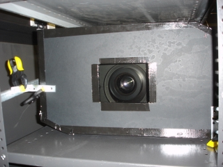 My M.Sc. student Graeme Phillipson did an excellent job of aligning the filters with this minimal equipment, but any misalignment could potentially worsen the ghosting — to minimise ghosting it is obviously important that the two polarisers should be at exactly 90 degrees to each other. Also note that these measurements were taken before gamma correction had been applied, and with a photometer due for its annual recalibration. However, the actual luminances are irrelevant: all that matters is whether they change as a function of the image on the “wrong” projector.
The first test I did was to put up constant luminance fields across the whole screen, a different luminance in each projector. I then measured the photometer’s output as a function of the signals sent to the two projectors. The results are shown below.
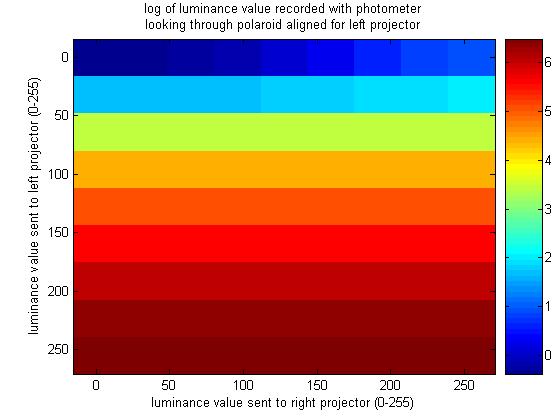
Clearly, the light output depends almost exclusively on the light projected by the left projector (the one aligned with the polariser through which the photometer is viewing the screen), and very little on the light projected by the right projector. This suggests that ghosting is not a major problem.
Let’s look at this data in more detail. First of all, to convert the signals (0-255) sent to the projectors into luminances, I took the luminance corresponding to level J to be the luminance measured by the photometer when both projectors are set to J (remember this display is not yet gamma-corrected), and then expressed everything in terms of the maximum luminance. To compare the different luminance levels, I normalised each row in the above figure by its value in the first column, i.e. I expressed each photometer measurement as a fraction of the value recorded with the same left-projector setting when the right projector was set to black. I then plotted how this varied as a function of the setting of the right projector. Solid lines are the means of 3 interleaved measurements; dotted lines show +/- SEM. The legend shows the luminance from the left projector.
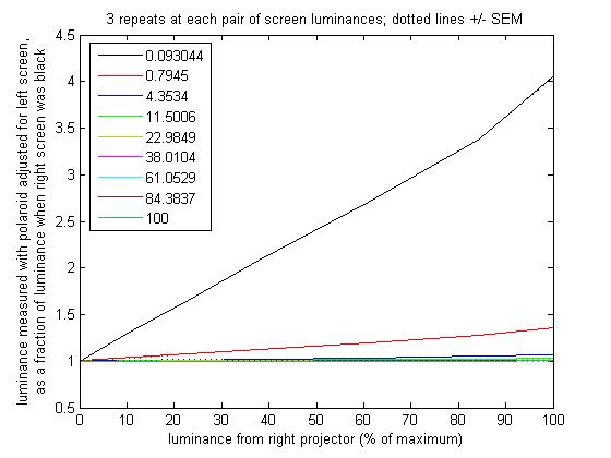
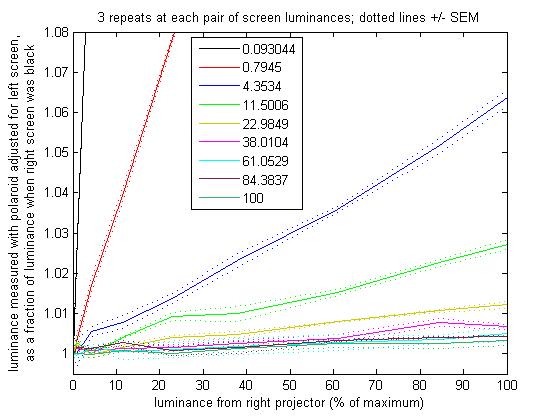
If the left projector is bright, at more than 4% of its maximum luminance, then there is very little ghosting. For example, if the left projector is at 4% of maximum output, then the photometer records 6% more when the right projector is at 100% than when it is at zero. A more realistic situation is when the left projector is at 50% (gray level). Then the photometer records just 0.5% more when the right projector is 100% (white) than when it is 0 (black). At low luminance levels, though, the system fails completely. If the left projector is black, then the left eye receives 4 times as much light when the right projector is white vs when it is black. On the other hand, this is the most extreme example one could possibly have, and not very relevant to experiments.
It then occurred to me that these ganzfeld stimuli were perhaps unsuitable. For example, the fact that the “left=black” curve in the figures above is not flat (black line) might actually not be due to ghosting, i.e. failure of the polarisation. Maybe enough of the bright light from the right projector is being reflected off the wall (hence depolarised), then back onto the screen, and so back into the projector. Maybe this contributes to the factor of 4 difference when the left projector is black.
Patch stimuli
I therefore redid the measurements with a more experimentally-relevant stimulus. Here, both projectors were set to the same background colour, and the photometer output was measured. Then a small square was displayed on the right projector, in a foreground colour, positioned so that the photometer was pointing straight at it, and the photometer reading was taken again. If there were no ghosting, these two readings would be the same. The results are displayed below — helpfully in a slightly different format; this time I have plotted the difference in results between when there was and was not a square in the right eye, and normalised these by the response without a square. This should be zero everywhere. As before, it fails completely when the background luminance is very low:
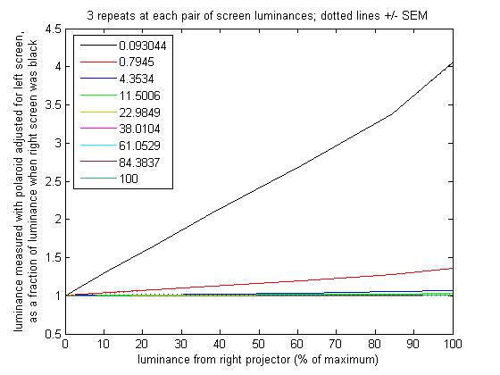
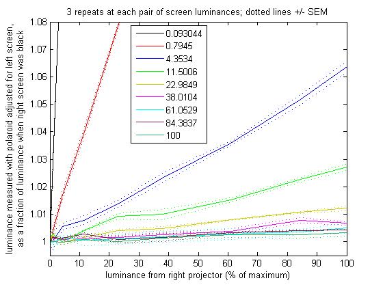
This implies that, if you use a random-dot stimulus with white dots on a black background, the white dots bleed through into the wrong eye, causing a four-fold increase in luminance there. This sounds very devastating, but when I have looked at such a stimulus, I have been unable to see the ghost dots. This is because the ghosted dots may have four times the luminance of the black screen (2.3cd/m2 vs 0.53 cd/m2), but both appear as black next to the “real” white dots, whose luminance is nearly 300 times that of even the ghosts (612 cd/m2).
What is the situation with a random-dot stimulus consisting of black and white dots on a gray background? Suppose the background is 62% of maximum (380cd/m2, since this was one of the values I have data for), and the white dots are as bright as possible, 612 cd/m2. Then the ghost of a white dot has a luminance of just 381 cd/m2, an increase of just 0.25% over the background luminance. Suppose the black dots are as dim as possible, 0.53 cd/m2. Then the ghost of a black dot has a luminance of 379 cd/m2, again representing a decrease of about 0.25% on the background luminance. When I’ve checked informally in my set-up, I cannot see the ghosts of white and black dots on a gray background. However, these measurements suggest I should be able to. I’ve looked up human contrast thresholds, and under bright illumination they are better than 0.5% across a wide range of spatial frequencies. 380 cd/m2 mean luminance should count as bright illumination, so I should be able to detect the ghosts if I did a formal psychophysical experiment.
Perhaps the simplest way of summarising the ghosting is to say that about 0.3% of the light shining from the right-eye projector gets through to the left eye. Admittedly in making this estimate I assumed the luminances of the two projectors are the same, which is unlikely to be exactly true, but then I am just after a ball-park figure at this stage.
2nd June 2006
As part of adjusting the gamma correction, I also took the following data
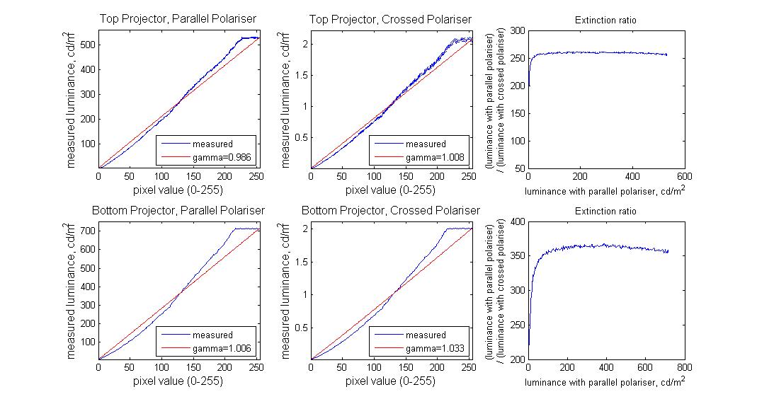
In the top panels, the lines look thicker because I took 5 measurements at each pixel value, and plotted mean +/- SD. I didn’t bother with this for the bottom projector.
It’s interesting to see that the amount of light getting through (1/extinction ratio) is not a fixed percentage of the incident light — at very low luminances, much higher percentages of the “wrong” light get through the polariser. Still, over a wide range of luminances the extinction ratio is very good — around 300, i.e. the 0.3% estimate I made above.
The poor extinction ratios at low luminances are not a problem for my applications. I only envisage using low levels like that to display black regions of a stimulus with much brighter overall luminance (e.g. black and white dots on a gray background). As noted above, a “ghost” black dot is still far dimmer than the gray level, and so is unlikely to be visible.
The extinction ratio is rather sensitive to the exact position of the photometer. I took a previous set of measurements in which the photometer was angled pointing upwards towards the top of the screen, and here the extinction ratio was worse for the bottom projector: around 150 instead of the >350 obtained here. I believe this reflects the degradation away from normal incidence. Light from the bottom projector had struck the screen at a relatively large angle, and thus at the top of the screen, the light from the bottom projector was more depolarised than that from the top projector. It is encouraging that even in this non-optimal case, the extinction ratio was better than 100 (
31st October 2006
I also looked at the extinction ratio for the three colours separately. Because this was done at the same time as checking the gamma correction, it’s on the gamma-correction page, here. There was little difference between the three colours (blue had poor extinction ratio, but this seems to be related to its much lower luminance as measured by the photometer — which is not a chromometer).


