


 This is the tricky business of aligning the projectors so that both images are the same size, rectangular on the screen and superimposed on one another.
When I first started researching possible solutions for stereo display, I was expecting to have to use a beam-splitter to get the two projectors’ images precisely superimposed. However, I found that high-end projectors have a lens shift function which shifts the image up and down (and/or left and right) without distorting it. The appropriate amount of “keystoning” is applied optically, so that the image remains rectangular on the screen. My Matrix 2500 projectors sit on shelves on top of one another, roughly equidistant from the viewers’ eyes, and vertical lens shift is used to bring the two images into registration. One thing to bear in mind is, large projectors generate significant amounts of heat and need to have enough space around them. My projectors need 20cm vertically between them and 1m behind them. This means that the projection throw distance is limited to around 1.7m given the size of my lab. The combination of short throw distance and far-apart projectors means tha t quite a lot of lens shift is needed.
Large amounts of zoom and lens shift distort the image
 I’ve found that, if I use zoom to make the images as large as possible, there is significant distortion at the top and bottom of the images. The top and bottom edges of the image sag in towards the centre, so lines which should be horizontal instead start to develop a U-shaped bend. When you then use lens shift to move the image down in the lens, horizontal lines near the top of the image remain fairly flat, while lines at the bottom bend up in the middle. For the other projector, lens shift is used to bring the image up relative to the lens, so lines at the top of the image bend down in the middle, whereas lines at the bottom remain flat. This makes it impossible to get horizontal lines perfectly aligned — in both cases, you are trying to superimpose a flat line on a curved one. I think there is also a similar, weaker effect on vertical lines too. While this effect is very small — a couple of pixels — it’s nevertheless quite serious for my purposes, and would require ugly correction in software. Fortunately, this effect goes away when I bring the zoom right down so the images are as small as possible. This then requires large amounts of lens shift to bring them into registration, but apparently this introduces much less distortion than smaller lens shift with a larger image. I don’t pretend to understand the optics here; I’m just glad to report that now, “horizontal” lines remain horizontal right across the image, and it is possible — with some time and trouble — to bring the two images into excellent registration. This is one of the attractions of a passive polarisation system: one can immediately see the quality of the alignment, and so any accidents which affect the alignment will be quickly picked up.
 Bringing the images into registration
For symmetry, I wanted to have both projectors in exactly the same state, but unfortunately the zoom and lens-shift are uncalibrated. To achieve this, I started off by zooming each image as large as possible, and then counting down the same number of clicks for each projector. Then I knew that any remaining difference in image size was due to differences in throw distance. I moved the projectors back and forth on their shelves until the images were as nearly as possible the same size, meaning that both projectors were the same distance from the screen. Similarly, I tried to ensure that both projectors had roughly the same value of lens shift (up for the bottom projector and down for the top one, obviously). This is a rougher assessment, because it’s a bad idea to move the lens-shift out to the furthest possible value — the projector has a tendency to jam there, and then lens-shift, focus and zoom all stop functioning (I’ve got them working again by taking the front off the projector). After this initial adjustment, both projectors were at least roughly in equivalent zoom and lens-shift states, and at the same distance from the screen.
To help with the alignment, I project a grid on each screen to act as a reference. I project it in red with one projector and blue with the other, so I can see which image is which. I make each gridline is 3 pixels wide, white-black-white. This makes a misalignment of even 1 pixel quite obvious, because the gridlines appear coloured.
I’ve found it’s best to start by trying to get the screen as close to vertical as possible. I then try and adjust the projectors so the gridlines are vertical or horizontal on the screen. As noted above, the image can get very slightly distorted at the edges of the lens, meaning that lines which should be horizontal are actually slightly bowed. While very hard to spot by eye, these subtle distortions make it impossible to align the images accurately. So you really want reference lines on the screen, which you can compare with the image and check that the image gridlines are truly horizontal and vertical all across the image, with no keystoning, tilt or bowing.
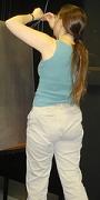
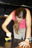
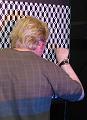
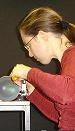
The first time I set my system up, I achieved these reference lines by covering the screen in wrapping-paper with a geometrical design that provided ready-made references for horizontal and vertical. Once you have got the up-down lines on the wrapping-paper vertical with a plumbline, then the left-right lines will automatically be horizontal. The picture on the right shows Graeme checking the alignment with this system. Subsequently, I found a much nicer solution using a device that projects laser cross-hairs, automatically adjusting itself to be aligned with gravity (I bought the AutoCross Laser 2 from LaserLevel. In the pictures, you can see the red laser crosshairs plus the projected grid, and Graeme checking their alignment. Wearing the red glasses supplied with the laser level isn’t really necessary, but does help to make the crosshairs more visible. This is a much nicer and easier system than using plumblines and wrapping-paper! We also used the laser to check that the screen was vertical, shining the laser cross-hair onto the edge of the screen and verifying that it hit the screen all the way down.
After setting up the wrapping-paper, I look at each projector’s image in turn, focus it on the screen, and try and get both the horizontal and vertical gridlines parallel to the vertical and horizontal lines on the wrapping-paper. To begin with, the image usually shows some keystoning (ie it appears trapezoidal, not rectangular), because the projector beam is not quite square on to the screen. I nudge the projector left or right to remove the horizontal keystoning, and twizzle its legs up and down to remove the vertical keystoning and any overall rotation of the image. Once this has been done for both images separately, I turn on both projectors and make sure both images are the same size using zoom, and use lens-shift to superimpose them vertically.
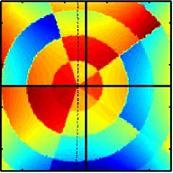
Here I’ve shown the sort of alignment I achieve. This is the result Graeme and I achieved after a couple of hours fiddling. These pictures show a yellow and cyan grid superimposed — you can see a larger version by clicking on them. The first picture shows noticeable misalignment at the top-left corner — unfortunately the yellow grid has come out much dimmer, but especially in the larger version you can see that there is a misalignment of 2 pixels horizontally at the top-left. The lower grid shows the much better alignment achieved over the rest of the 70cm x 55cm image — here the two grids superimpose. It also shows the laser cross-hairs, showing that the gridlines are truly vertical and horizontal.

